Exporting and Importing SharePoint List form PowerApps Package

One of the challenges of using PowerApps to develop a SharePoint list form is portability. In most enterprises, developers use various environments for development, testing and production. In this blog post, we will look into the details of exporting a SharePoint list form PowerApps app from one SharePoint site to another.

The following steps describes the details on deploying a customized SharePoint list form PowerApps app from one environment /SharePoint site to a different environment/SharePoint site.

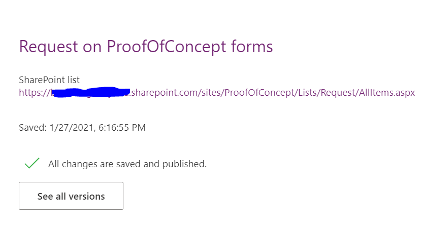
Step 1- Save the SharePoint List/Library Power app form. Click “See all versions”. Then click “Export Package”.

Step 2- Open the Exported package in file explorer and go to the Microsoft.PowerApps/apps/{Numeric folder}

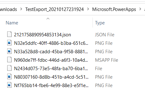
Step 3- Copy the json file in the above folder and paste it into a temporary folder

Step 4- Open the json file using Visual Studio Code or your favorite editor.

Step 5- Go to the destination SharePoint site and get the URL and listId. ListId can be found from the List setting URL.

Step 6- Search for the “dataset” key and replace the List Guid with the destination ListId

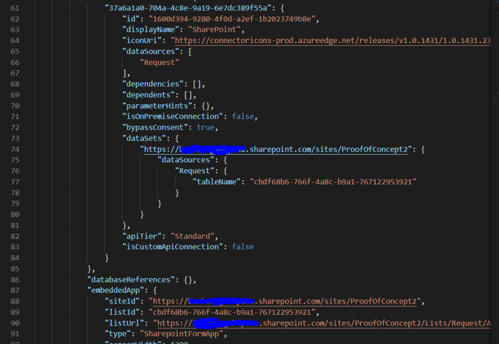
Step 7- Search for “embeddApp” key and replace the Site Url, List Guid with the destination Site Url and List ID ( Step 5)

Step 8- Save the json file

Step 9- Copy the updated json file and paste it in the Zip folder.

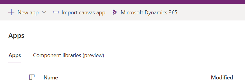
Step 10- Go to https://make.powerapps.com.

Step 11- Click “Import Canvas app”

In conclusion, by updating the json file in the PowerApps package, it is possible to deploy PowerApps SharePoint list form app from one environment to another.

How to determine Software Complexity

Occasionally businesses rewrite application software to retool, enhance performance, or re-platform to the cloud. Rewriting software applications starts with determining the complexity of existing applications. In this blog post, I will highlight the steps to determine software complexity and application re-write project planning.

The first step to determine software complexity is to identify the various parts. These parts can be UI layer, Service layer or Backend (Data storage). Not all application software necessarily have all these layers. Modern applications can have only UI and Service layer, or just a UI layer.

The second step is to identify the complexity variables at each layer. For example in the UI layer, the number of UI controls, the number of validation functions are complexity variables. For the Service layer, the number of classes, the number of functions can be complexity variables.

The third step is to associate weight corresponding to each of the complexity variables identified in step two. The weight is a relative number to determine how complex the variable is. The weight is a multiplier of the complexity variable like x1, x1.25, x1.5, x1.75, x2.

The forth step is to put the complexity variables in a tabular format with the variables as rows and count, complexity weight, total complexity as columns. An example is below.

Fig 1- Complexity Metrics table

The last step is to determine the complexity value, either simple/medium/complex, based on the value of the [Total Complexity (count*weight)]. Complexity value determination depends on the nature of the application, the team composition, and the technology or tool chains used.

In conclusion, knowing existing application complexity helps to estimate the effort to rewrite the application, re-platform the application, or migrate the application from one version to another.

Thoughts on Software Development Project Management

Over the years, I have been driving various software development projects. These projects are from small to large; simple to complex; from a few weeks to a few years. In this blog post, I will illustrate the common thread that makes a software product and project successful. I define a successful product as a running software product that the stakeholders are happy with that is completed on time and budget.

Most custom software development projects start with high level discussion with the product user/owner. This discussion eventually leads to product features, project scope, project release plan and more. In some agile software development frameworks certain terminologies are used to describe the above work products- Epic, User stories, Issues etc..

If the project is medium to large, it can be decomposed to multiple mini projects (releases) with distinct boundaries in terms of features, timeline and resources.

Decomposing the software project to a number of releases that can be implemented and delivered by a two or three developers is the most important factor in the success of a software project. Each of these releases are independently deployable with its own project plan with many iterations. Each iteration is similar to a sprint in the scrum framework. In each iteration, the 2 developers work closely with the end users and product owner to hash the details of the requirements, design and develop the solution.

Limiting the development team to 2-3 members increases agility, open communication and focus. This also speeds up the feedback loop between developers and product users. The development team can engage in discussion with the product user/owner multiple times a day. Interacting with product user/owner is a very important part of the development teams task. The discussion with the product user/owner revolved around clarifying the requirements, demoing the product, and setting the expectations.

Each product release consists of one or more iterations. Each iteration result in a functioning software that may or may not be put in production. Duration of iteration ranges from 2 to 3 weeks. The purpose of each iteration is to produce working software. Each iteration involves clarifying requirements, designing and developing solutions, demoing the solution, and gathering feedback from the product user/owner.

It is important to keep the development team intact for the entire period of the product release. The purpose of the release is to produce a functioning software that can be deployable with one or more features that can be used immediately by the product user/owner.

In conclusion, the central part for a successful software development project is scoping the project into multiple, independent , simple mini-projects (releases) that can be handled by a team of 2-3 developers.

Creating Teams Channel Meeting Link in Power Automate

This blog post discusses how to create a teams channel meeting link in Power Automate which involves constructing a teams meeting url for a particular channel. This has practical applications in sending out automated meeting invites based on certain events. For example, automating the creation of dynamic teams channel based on user input and post/send the channels meeting link to users.

  1. The first step is declare workflow variables to hold the TeamsID, TenantID, ChannelID, MeetingOrganizerID, and Url for the teams channel meeting.

2. Get the list of Channels using [List channels] action.

3. Select a specific Channel, for example General.

4. Set the TeamID, TenantID, and ChannelID variables.

TeamID is set to- first(slit(last(split(Items(‘Apply_to_each’)[‘WebUrl’], ‘groupId=’)), ‘&tenantId’)). TenantID is set to- last(split(Items(‘Apply_to_each’)[‘WebUrl’], ‘tenantId=’))

5. Get Teams Meeting organizer using [Get user profile] action.

6. Set teams Channel Meeting url. The format is – Https://teams.microsoft.com/I/meetup-join/[ChannelID]/0?context={“TId”:”TenantID”,”OId”:”OrganizerID”}. If graph api is used to send the message to email, consider encoding { ” : ,} characters.

7. Send the meeting url in an email or post it a teams channel.

In conclusion, using power automate, channel meetings can be set up dynamically, and users can join the meeting.

Using Graph API with Power Automate to create Custom Actions

In this blog post, we use Graph API’s to develop custom actions in Power Automate. Custom actions are any piece of Power Automate functionality that are not provided out-of-box. Microsoft is constantly updating the out-of-box actions in Power Automate. However, there are some instances where the business needs may not be met with only those actions. These use cases require custom development of actions using Graph API and Http Request Action (aka – Http with Azure AD).

To illustrate custom action development, we use posting @Channel mentions in a Teams channel using Graph API and Invoke Http Action.

  • The first step is to declare variables for TeamsID, ChannelID and ChannelPostUrl.
  • Get the channel to post messages using the action – List channels action
  • Set the values of the variables for TeamsID, ChannelID, and ChannelPostUrl
We find the value of TeamsID using the following expression from the [‘WebUrl’] property of Channel: first(slit(last(split(Items(‘Apply_to_each’)[‘WebUrl’], ‘groupId=’)), ‘&tenantId’)) .
  • Use graph API’s POST method in the Invoke an HTTP request action.

In conclusion, using Power Automate and Graph API, the potential for developing custom actions are limitless.

Process Automation using Power Automate with SharePoint Online

In this blog post, we will discuss best practices to develop process automation using Power Automate with SharePoint Online.

Power Automate is a process automation (workflow) tool for the Microsoft 365 (O365) platform. It interacts with almost all O365 apps and many more online services through connectors. One widely used tool for collaboration is SharePoint Online, and Power Automate has many connectors to SharePoint Online to perform various Actions and Triggers.

In developing Power Automate, it is best practice to keep re-usability, extensibility and maintainability in mind just like writing any piece of software. One way of achieving re-usability and maintainability across various environments is through parameterizing the Inputs instead of hard-coding. For example, a url of a SharePoint site can be parameterized so that the rest of the code is intact when moving the Power Automate from development to QA to production environments.

Below is a simple use case to illustrate the development of Power Automate targeting Dev/QA and production environments of a SharePoint Online site. The use case creates a list item on a SharePoint Online list.

The first step is to initialize variables for the Site Url and List Name as shown below. Depending on the target SharePoint environment, the value of the SiteUrl variable is set to Dev, QA, or Production. This makes the deployment of the workflow consistent across multiple environments.

The second step is to create the item in a SharePoint site.

In conclusion, parameterizing power automate inputs makes deployment across multiple environments consistent.

Info-path forms and SharePoint Designer Workflow Conversion to Nintex Forms and Workflows

In this blog post, we discuss best practices for converting Info-path forms to Nintex form and SharePoint Designer workflows to Nintex Workflows. This approach can be applied to any sort of software conversion, software rewrite, or software upgrade.

  1. Write PowerShell Scripts to get the inventory of info-path forms, and SharePoint Designer workflows with associated metadata which may include number and type of UI controls or actions.
  2. Develop a SharePoint Site to Manage the waves of conversions. The site manages the day-to-day tasks of the conversion process such as Assignment for Conversion, Status of the conversion, and a form to track issues on the conversion. It can include workflows to notify end users about the status of their sites.
  3. Create a staging environment for the conversion. This environment is used to convert the Info-path forms and designer workflows; one site collection per wave of conversion is sufficient.
  4. Copy the List/Libraries to the staging environment.
  5. Determine the complexity of the form and workflows. The Info-path form complexity is determined by the number of UI Controls and the weight of the Control Types. For example, a form having 1-6 UI controls is simple, 7-12 is medium, more than 13 is complex. Complexity of designer workflows is determined by the number and type of actions in the workflow.
  6. Prioritize Info-path forms and designer workflows inventory into waves. Duration of a wave is typically 2 weeks. Within these 2 weeks development and testing by the development team is completed. The wave will be handed over to end users for validation, which can last up-to 2 weeks.
  7. Assign conversion tasks to development teams. Each developer in the conversion team picks and assigns several forms/workflows for each wave.
  8. The conversion (development) team maintains the status of each form and workflow conversions.
  9. Send automated workflow notification to end users. After development and testing is completed by the conversion team, the status of the form and workflows is set to “Ready for validation” which sends notification to end users for validation.
  10. End users log any defects during validation to a defect tracker. The defect will automatically be routed to the developer that was assigned to work on the conversion.

The above 10 step approach is based on my personal experience in leading the conversion of info-path forms and designer workflows. The approach proved to be successful and can be applied with some enhancement to other types of software conversion, upgrade, re-write initiatives.

M365 (O365) -Teams and Power Automate Integration

With Microsoft Teams becoming a defacto enterprise communication and collaboration tool, more and more firms are using Teams with other M365 (O365) productivity tool sets. One of the most widely used productivity tool is Power Automate (formerly Ms Flow). In this blog post, I will illustrate how to use Power Automate to dynamically create a Teams Channel in response to user request and send a link of the channel to the user. This use case has practical application in areas of customer support, ticket management and incident escalation.

The first step is to create a data submission form in your favorite form designer like Ms Forms, Power Apps, Nintex Form etc.. this exercise uses Ms Forms. Create the process automation using Power Automate. Since the flow is triggered based on submission of the form choose instant flow template.

  1. Choose a name for the flow, and set the trigger as below.

2. Declare a variable to hold the Teams Channel url.

3. Get response details submitted to the form.

4. Create a Channel in the Team.

5. Wait 15-20 seconds until the channel creation is completed. Error handling logic can be added here if channel creation fails.

6. Get all the channels from the Team.

7. Filter the Channels so that the recently created channel is returned. [Filter array] Action can be used here. The Channels are filtered based on [Channel Name] equal to the name given when the channel is created in (step 4). To get the name of the channel use the expression: body(‘Create_a_channel’)?[‘displayName’].

8. Loop through the filtered array and get the url of the channel. Use the expression item(‘Apply_to_each’)[‘webUrl’] to get the channel link.

Send the Channel link to the submitter using various means like email, post message @mention etc..

The overall Power Automate is below.

In conclusion, integrating MS Teams with Power Automate opens up lots of Automation in the Collaboration and Communication space of M365 (O365).